MEscope

MEscope - Vibration Analysis System

MEscope ODS

MEscope makes ODS and Modal jobs easy. MEscope VES can sweep through a set of time history data and animate the response of a structure, or show the structure’s behavior while dwelling at a specific time or frequency.

VES

With MEscopeVES, looking at ODS's is as easy as moving a cursor through your measurements and observing an animated display of your data. MEscopeVES can sweep through a set of time histories and animate the response of a structure, or show the structure's behavior while dwelling at a time, frequency or machine order. MEscopeVES has been specifically designed to make it easy for you to observe and analyze a variety of vibration, acoustic, and strength of materials problems in machines and structures. It utilizes multi-channel time or frequency domain experimental data, acquired during the operation of a machine, or the static or dynamic loading of a structure.

Overview

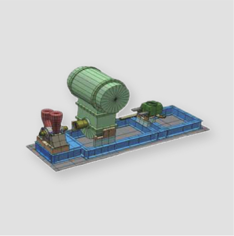
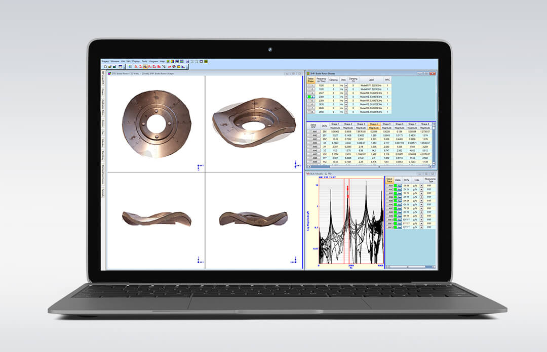
The MEscopeVES Visual Engineering Series of software packages and options makes it easier for you to observe and analyze noise & vibration problems in machinery and structures using either experimental or analytical data. With MEscope, you can import or directly acquire multi-channel time or frequency data from a machine or structure, and post-process it. Its industry-leading interactive 3D animation allows you to observe order-related operating deflection shapes from running machinery, resonant vibration and mode shapes from real structures, acoustic shapes, and engineering shapes directly from acquired data. In addition to its photo-realistic interactive animated display, MEscopeVES contains state of the art tools for performing: • FRF-Based Modal Analysis • Operational Modal Analysis • Vibro-Acoustic Analysis • Dynamics Modeling & Simulation • Structural Dynamics Modification • Experimental FEA

VT-620 ODS

An animated ODS shows how your machine or structure is moving in slow motion. By animating the ODS’s of a structure, you can see what can’t be seen any other way; a structure’s overall motion and the motion of one part relative to another. Excessive vibration levels and loose or damaged parts are easily identified from an animated ODS display. Visual ODS™ lets you see how a machine or structure is moving by animating ODS’s directly from a set of time of frequency domain experimental data. As an example of the practical use of Visual ODS™, a blower fan located on the roof of a building was experiencing severe vibration, throwing off belts, and creating high noise and vibration levels throughout the building. All attempts to balance the fan had not solved the problem. A set of ODS data was taken while the fan was running, using a 2-channel analyzer with a tachometer signal. A set of Peak & Phase data at the operating speed of the motor was acquired. The animated ODS showed that the base of the motor at the end opposite the belt was moving out of phase with the motor. Removing some paint from the base of the motor revealed a previously undetected crack in the motor mount. After repairing the crack, the fan was re-balanced and the severe vibration and noise problem was solved.

VT-570 ODS

The Visual Modal™ package combines all of the features of the Visual ODS Pro™ package with the features of the VES-4000 Basic Modal Analysis option. The Basic Modal Analysis option provides all of the tools you need for extracting modal parameters from experimental vibration measurements (FRFs). With Visual Modal™ you can identify the frequency, damping & mode shape of the modes of a structure from experimental data.

Modal parameter estimation (curve fitting) is done in three steps; 1) count the number of modes using a Mode Indicator function, 2) estimate the modal frequency & damping for each mode, 3) estimate a modal residue (a mode shape component) for each mode & each measurement.

VT-540 ODS

The Visual SDM™ package combines all of the features of the Visual Modal™ package with the features of the VES-5000 Structural Dynamics Modification option.

Once you have identified and quantified a resonance problem in a machine or structure, the next question is, “How can the structure be modified to fix the problem?”

Visual SDM™ helps you quickly evaluate alternative solutions to resonance problems by adding additional tools to the modal analysis features of a Visual Modal™ package. The Structural Dynamics Modification (SDM) method allows you to examine the effects of a variety of potential structural modifications on the resonances of a structure without actually having to make the physical modifications. The resonances (modes of vibration) of a machine or structure depend on its physical properties (geometry, density, elasticity, boundary conditions, etc.). Changing the physical properties of a structure by adding modifications such as stiffeners, brackets, tuned absorbers or other modifications, will directly affect its modes. The SDM method uses industry standard finite elements such as springs, masses, dampers, bars, plates, and solids to model the modifications. These modifications, together with the modes of the original (unmodified) structure, are used to calculate the new modes of the modified structure.

In the example shown below, a stiffener was added across the bottom of an aluminum panel. Adding the stiffener replaced the first mode of the structure (a bending mode at 73Hz) with a torsional mode at 94Hz. The torsional mode was the second mode of the original structure but was not affected by the rib stiffener. Without the added stiffener, machinery in the vicinity operating at 4000-4500 RPM would excite the first bending mode of this panel causing it to resonate. Adding the stiffener not only eliminated the mode at 73Hz, but also eliminated another mode at 143Hz, thus removing a potential resonance problem at 2X RPM as well.